Payload Retrieval Subassembly
Concept 1

Concept 1 Drawing
Side View |
Top and Front Views |
|
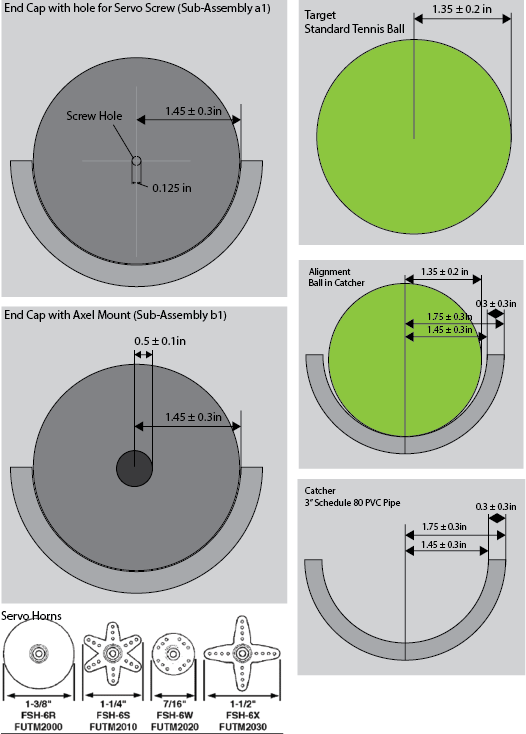
The right column pictures the a side view of a tennis ball resting in a half PVC pipe with approximate dimensions. The left column pictures end-caps that prevent the ball from rolling out of either side and couple the assembly to a servo and to a bearing.
|
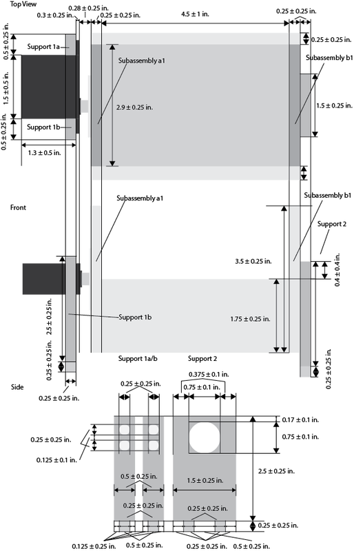
Pictured below are top and front views of the retrieval assembly and a side view of the supports that could the assembly to the base of the vehicle.
|
Concept 1 Version 1 Cutting plans
|
This plan, designed for manufacturing using a laser engraver, is the first prototype of Version 1 of Concept 1 for Subassembly 1, the payload retrieval assembly. The large discs, subassemblies a1 and b1, are designed to be glued inside the edges of a 3" schedule 80 PVC pipe in order to allow for a servo and an axle to attach to the scoop. The axle pieces are designed to be glued together vertically to form a 0.5 in. diameter cylinder to form an axle to run from subassembly b1 to support 2. Supports 1a and 1b are designed to hold a RadioShack 2730766 servo. The horn of that servo shall be glued and screwed to subassembly a1. The screw hold tests exist to allow testing of various dimensions of screw holds in case the once centered in subassembly a1 is incorrectly sized. Support joint tests exist to test the dimensions of the sockets that the feet of the supports will be glued into on the main chassis. A 1x1 inch box is included to ensure proper scale throughout the manufacturing process.
|

|
