Version 2
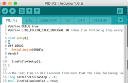
Version 2 utilizes tabs for organization of code, which results in separate .ino files in the same program. Files are labeled based on which platform they are a part of (transmitter or receiver). The Arduino IDE takes care of ensuring that all files are in the same namespace.
PID_V2.ino (Main File on vehicle)
| pid_v2.ino |
#define DEBUG true
#define LINE_FOLLOW_STEP_INTERVAL 10 //Run line following loop every 10 milliseconds
void setup()
{
#if DEBUG
Serial.begin(9600);
#endif
lineFollowSetup();
}
//The last time in milliseconds from boot that the line following loop ran
long lastLineFollowStep = -1;
bool lineFollowEnabled = true;
void loop() {
long mils = millis();
if (lineFollowEnabled) {
//Run the loop once every 10 milliseconds
if ((mils - lastLineFollowStep) >= LINE_FOLLOW_STEP_INTERVAL) {
//Run the loop
lineFollowStep();
//Store the time that the loop ran
lastLineFollowStep = mils;
}
} else {
halDrive(0, 0);
halDrive(1, 0);
}
#if DEBUG
if (Serial.available()) {
Serial.read();
lineFollowEnabled = !lineFollowEnabled;
}
#endif
}
HAL.ino (Tab on Vehicle)
| hal.ino |
/**
* The Hardware Abstraction Layer (HAL) interfaces a single method call
* to control a motor with whatever motor controller layer is being used.
* Early in development, the Ardumoto shield was used. Later, a cutom
* H-Bridge was used. The HAL removes the need to modify PID or LineFollowing
* code further than KP and KD weights.
*/
#define ARDUMOTO true //True if the motor controller is an ardumoto
#define HAL_ENABLED true //True if motors should run
#define HAL_DEBUG true //True if debug messages should be shown
//Motor integer values
#define MOTOR_A 0
#define MOTOR_B 1
//-------ARDUMOTO----------
#if ARDUMOTO
// Clockwise and counter-clockwise definitions.
// Depending on how you wired your motors, you may need to swap.
#define CW 0
#define CCW 1
// Pin Assignments
const byte PWMA = 3; // PWM control (speed) for motor A
const byte PWMB = 10; // PWM control (speed) for motor B
const byte DIRA = 9; // Direction control for motor A
const byte DIRB = 8; // Direction control for motor B
/**
* Setup lower level HAL components
*/
void halSetup() {
#if HAL_DEBUG
Serial.println("Setting up HAL...");
#endif
setupArdumoto();
#if HAL_DEBUG
Serial.println("HAL setup complete.");
#endif
}
/**
* Drives a given motor at a given speed
*/
void halDrive(int motor, int spd) {
#if HAL_ENABLED
driveArdumoto(motor, (spd < 0 ? CCW : CW), (byte) abs(spd));
#endif
}
/**
* Returns the maximum value for a motor
*/
int halGetMax() {
return 255;
}
/**
* Returns the minimum value for a motor
*/
int halGetMin() {
return -255;
}
/**
* Return a value where the motor does not spin
*/
int halGetZero() {
return 0;
}
// driveArdumoto drives 'motor' in 'dir' direction at 'spd' speed
void driveArdumoto(byte motor, byte dir, byte spd)
{
if (motor == MOTOR_A) {
digitalWrite(DIRA, dir > 0 ? HIGH : LOW);
analogWrite(PWMA, spd);
}
else if (motor == MOTOR_B) {
digitalWrite(DIRB, dir > 0 ? HIGH : LOW);
analogWrite(PWMB, spd);
}
}
// setupArdumoto initialize all pins
void setupArdumoto() {
#if HAL_DEBUG
Serial.println("Setting up Ardumoto...");
#endif
// All pins should be setup as outputs:
pinMode(PWMA, OUTPUT);
pinMode(PWMB, OUTPUT);
pinMode(DIRA, OUTPUT);
pinMode(DIRB, OUTPUT);
// Initialize all pins as low:
digitalWrite(PWMA, LOW);
digitalWrite(PWMB, LOW);
digitalWrite(DIRA, LOW);
digitalWrite(DIRB, LOW);
#if HAL_DEBUG
Serial.println("Ardumoto Setup Complete.");
#endif
}
#endif
LineFollow.ino (TAB ON VEHICLE)
| linefollow.ino |
/**
* Abstraction of line of following code optimized for closed-loop control
* within a larger system.
*/
#define LINE_FOLLOW_DEBUG true
//The PID proportional weight to apply to the error
#define KP 0.05
//The PID derivative weight to apply to the error
#define KD 0.7
//The PID setpoint of the system
//This is 3000 because the QTR reads 0-6000 with 3000 at the center
#define SETPOINT 3000
//The default set spead for each motor 0-100
#define MOTOR_A_SPEED 220
#define MOTOR_B_SPEED MOTOR_A_SPEED
/**
* Runs the setup methods for all of LineFollowing's dependencies
*/
void lineFollowSetup() {
#if LINE_FOLLOW_DEBUG
Serial.println("Setting up Line Following...");
#endif
//Setup dependenceis
qtrCalibrate();
halSetup();
#if LINE_FOLLOW_DEBUG
Serial.println("Line Following Setup Complete.");
#endif
}
//Variable outside of the step scope to store the last error
int lastPos = 3000;
/**
* Runs a single step of the control loop for line following. This should
* be called at very regular intervals to keep a consistant derivative value.
*/
void lineFollowStep() {
//Read position on line from QTR sensor
int pos = qtrGetPosition();
//Run PID on the new position
int output = pid(SETPOINT, pos, lastPos, KP, KD);
lastPos = pos;
#if LINE_FOLLOW_DEBUG
Serial.print("Position: ");
Serial.print(pos);
Serial.print("\tOutput: ");
Serial.print(output);
Serial.println();
#endif
//Calculate motor speeds
int outputA = MOTOR_A_SPEED - output;
int outputB = MOTOR_B_SPEED + output;
//If the motor speed exceeds the bounds, use max or min values
if (outputA < halGetMin())
outputA = halGetMin();
if (outputB < halGetMin())
outputB = halGetMin();
if (outputA > halGetMax())
outputA = halGetMax();
if (outputB > halGetMax())
outputB = halGetMax();
//Output new value to motors
halDrive(MOTOR_A,outputA);
halDrive(MOTOR_B,outputB);
}
PID.ino (TAB ON VEHICLE)
| pid.ino |
/**
* Abstraction of PID math
*
* Currently, only proportional and derivative math is implemented
* No steady-state errors have been present yet, so the integral
* componenet has not been implemented.
*
* setpoint - The ideal condition of the system
* sig - The input into the control loop (for instance, the QTR sensor reading)
* lastSig - The input into the control loop in the last step (used to calculate derivative)
* KP - weight of the proportional component of the error
* KD - weight of the derivative component of the error
*/
int pid(int setpoint, int sig, int lastSig, float kp, float kd) {
//Calculate error and last error from input signal and setpoint
int error = sig - setpoint;
int lastError = lastSig - setpoint;
//Perform the pid calculation by applying KP and KD weights
//to the error and the derivative of the error.
int output = kp * error + kd * (error - lastError);
return output;
}
QTR.ino (TAB ON VEHICLE)
| qtr.ino |
/**
* Abstraction for the QTR library optimized for the purposes of closed-loop
* PID linefollowing.
*/
#include <QTRSensors.h>
//Enables or disables debuging serial prints
#define QTR_DEBUG true
//Parameters for the QTR library
#define NUM_SENSORS 8 // number of sensors used
#define TIMEOUT 2500 // waits for 2500 microseconds for sensor outputs to go low
#define EMITTER_PIN 2 // emitter is controlled by digital pin 2
#define CALIBRATION_ITERATIONS 100// the number of times to call calibrate()
//Initialize the QTR library with the pin layout
QTRSensorsRC qtrrc((unsigned char[]) {
A0, A1, A2, A3, A4, A5, 4, 5
},NUM_SENSORS, TIMEOUT, EMITTER_PIN);
//A place in memory for the sensor values
unsigned int sensorValues[NUM_SENSORS];
/**
* Calibrates the QTR sensor array using the QTRSensors library's calibrate
* method.
*/
void qtrCalibrate() {
#if QTR_DEBUG
Serial.println("Calibrating QTR...");
#endif
//Perform the actual calibration
//Calibration takes about 10 seconds at 400 interations
//About 25ms per call
for (int i = 0; i < CALIBRATION_ITERATIONS; i++) {
qtrrc.calibrate();
}
#if QTR_DEBUG
//Print minimum values
for (int i = 0; i < NUM_SENSORS; i++) {
Serial.print(qtrrc.calibratedMinimumOn[i]);
Serial.print(' ');
}
Serial.println();
//Print maximum values
for (int i = 0; i < NUM_SENSORS; i++) {
Serial.print(qtrrc.calibratedMaximumOn[i]);
Serial.print(' ');
}
//Print completion message.
Serial.println("\nCalibration Complete.");
#endif
}
/**
* Returns the position of the sensor on the line ranging from 0-6000
* with 3000 directly centered on the line using the QTR Library's position
* method.
*/
int qtrGetPosition() {
return qtrrc.readLine(sensorValues);
}
RECEIVER.ino (TAB ON VEHICLE)
| reciever.ino |
#include <SPI.h>
#include "RF24.h"
#define RECIEVER_DEBUG true
#define COMMAND_SIZE 4
RF24 radio(6, 7);
byte TRANSMITTER_ADDRESS[] = "EAKJB_RECEIVER";
byte RECEIVER_ADDRESS[] = "EAKJB_TRANSMITTER";
const bool PIN_OUTPUTS[] = {
false, false, false, false, false, false, false, false, false, false, false, false, false, false
};
const bool PIN_ANALOGS[] = {
false, false, false, true, false, true, true, false, false, true, true, true, false, false
};
void recieverSetup() {
#if RECIEVER_DEBUG
Serial.println("Setting up Reciever...");
#endif
halSetup();
for (byte i = 0; i < sizeof(PIN_OUTPUTS); i++) {
if (PIN_OUTPUTS[i]) {
#if RECIEVER_DEBUG
Serial.print(i);
Serial.print(", ");
#endif
pinMode(i, OUTPUT);
}
}
//Initialize radio...
radio.begin();
//Set power level to low because communication is short-range
radio.setPALevel(RF24_PA_LOW);
//Open reading and writing pipes (addresses)
//Switch the addresses on the transmitter
radio.openWritingPipe(TRANSMITTER_ADDRESS);
radio.openReadingPipe(1, RECEIVER_ADDRESS);
//Start listening
radio.startListening();
#if RECIEVER_DEBUG
Serial.println("Reciever Setup Complete.");
#endif
}
void readAndProcessCommand() {
//Wait for the transmitter to send something
if (radio.available()) {
#if RECIEVER_DEBUG
Serial.print("Receiving command...");
#endif
//Initialize an array to hold the command
byte command[COMMAND_SIZE];
//Set to false if there is an error reading transmission
bool okay = true;
radio.read(command, sizeof(byte)*COMMAND_SIZE);
//If the transmission has more than 4 bytes, handle this as an
//error and throw out the additional bytes.
while (radio.available()) {
#if RECIEVER_DEBUG
Serial.println("Error reading command. Too many bytes.");
#endif
okay = false;
byte junk;
radio.read(&junk, sizeof(byte));
}
//Give a debug message and print the received command
#if RECIEVER_DEBUG
Serial.print("Done. Received: ");
for (byte i = 0; i < COMMAND_SIZE; i++) {
Serial.print(command[i], DEC);
Serial.print(", ");
}
Serial.println();
#endif
//Process the command
processCommand(command);
}
}
void processCommand(byte command[]) {
if (command[0] == 0) { //PING
#if RECIEVER_DEBUG
Serial.println("Ping not implemented yet.");
#endif
} else if (command[0] == 1) { //PIN CONTROL
//Check if the pin is valid and allowed
if (command[1] > 0 && command[1] < sizeof(PIN_OUTPUTS) && PIN_OUTPUTS[command[1]]) {
#if RECIEVER_DEBUG
Serial.print("Setting Pin ");
Serial.print(command[1]);
Serial.print(" to ");
#endif
//Check if the pin is analog
if (PIN_ANALOGS[command[1]]) {
#if RECIEVER_DEBUG
Serial.print(command[2]);
#endif
//If the pin is analog, write the value to it.
analogWrite(command[1], command[2]);
} else {
//If the pin is digital, go HIGH if the desired value is above 0.
if (command[2] > 0) {
#if RECIEVER_DEBUG
Serial.print("HIGH");
#endif
digitalWrite(command[1], HIGH);
} else {
#if RECIEVER_DEBUG
Serial.print("LOW");
#endif
digitalWrite(command[1], LOW);
}
}
#if RECIEVER_DEBUG
Serial.println(".");
#endif
} else {
//The pin is invalid.
#if RECIEVER_DEBUG
Serial.print("Invalid pin: ");
Serial.println(command[1]);
#endif
}
} else if (command[0] == 2) {
int spd = command[2];
if (command[3] > 0) {
spd *= -1;
}
halDrive(command[1], spd);
}
}
Transmitter_v2.ino (Main file on Transmitter)
| transmitterv2.ino |
#include <SPI.h>
#include "RF24.h"
#define COMMAND_SIZE 4
// Clockwise and counter-clockwise definitions.
// Depending on how you wired your motors, you may need to swap.
#define FORWARD HIGH
#define BACKWARD LOW
// Motor definitions to make life easier:
#define MOTOR_A 0
#define MOTOR_B 1
RF24 radio(7, 8);
byte TRANSMITTER_ADDRESS[] = "EAKJB_RECEIVER";
byte RECEIVER_ADDRESS[] = "EAKJB_TRANSMITTER";
void setup() {
//Initialize serial...
Serial.begin(9600);
Serial.print("Intializing transmitter...");
//Initialize radio...
radio.begin();
//Set power level to low becaue communication is short-range
radio.setPALevel(RF24_PA_LOW);
//Open reading and writing pipes (addresses)
//Switch the addresses on the transmitter
radio.openWritingPipe(RECEIVER_ADDRESS);
radio.openReadingPipe(1, TRANSMITTER_ADDRESS);
//Start listening
radio.startListening();
//Notify debugger that initialization has finished.
Serial.println("Done.");
}
void loop() {
int reading = analogRead(A0);
int reading2 = analogRead(A1);
// Serial.println(reading);
// Serial.print("Transmitting command...");
byte val;
byte dir;
if (reading>=512) {
val=map(reading,512,1023,0,257);
dir=FORWARD;
} else {
val=map(reading,511,0,0,257);
dir=BACKWARD;
}
byte val2;
byte dir2;
if (reading2>=512) {
val2=map(reading2,512,1023,0,257);
dir2=FORWARD;
} else {
val2=map(reading2,511,0,0,257);
dir2=BACKWARD;
}
Serial.print(val);
Serial.print('\t');
Serial.println(val2);
byte commandA[COMMAND_SIZE] = {0x02, MOTOR_A, val, dir};
byte commandB[COMMAND_SIZE] = {0x02, MOTOR_B, val, dir};
radio.stopListening();
radio.write(&commandA, sizeof(byte)*COMMAND_SIZE);
delay(80);
radio.write(&commandB, sizeof(byte)*COMMAND_SIZE);
radio.startListening();
// Serial.println("Done.");
delay(80);
}
