Versions
Version 1 |
Version 2 |
|
Version 1 is the first functional iteration of PID line following. It was used at runoffs on December 4th, 2015. The code works but is disorganized and does not follow the designed architecture below. It was difficult to modify and to maintain.
|
Version 2 is an intermediate version between the final competition version and Version 1. Where Version 1 was a minimum just to make line following work, Version 2 is a much more polished product. It demonstrates the designed organization detailed below and integrates components of both receiver code and line following code.
|
ARCHITECTURE
|
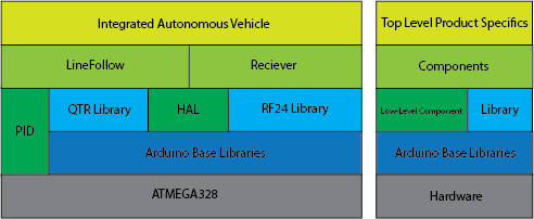
The Integrated Autonomous Vehicle utilizes multiple distinct programming layers allowing for abstraction, organization, and reusability. The final IAV code runs on top of line following and remote control receiver components that are non-specific to the specific task. These components were built on a low-level output hardware abstraction layer (HAL) insulates line following and remote control code from the underlying hardware specifics. PID is also abstracted into its own low-level component in order to allow for reusability. Low-level components and libraries run on top of the Arduino software platform, which runs on top of the ATMEGA328 process.
|
|
Scheduling
|
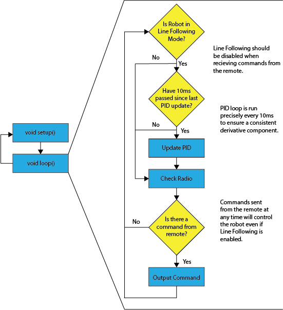
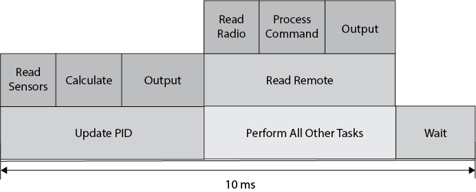
Special care is taken to ensure that the PID loop runs at a precise interval of 10ms. This matters because it is impossible to tune the derivative component accurately if the time between error measurements is inconsistent. This is not an issue for a program where the main loop contains only a PID loop; however, the program also contains code to read from the radio receiver and to process commands. As a result, special care is taken to ensure consistent execution of the control loop.
|
PID Block Diagram
|
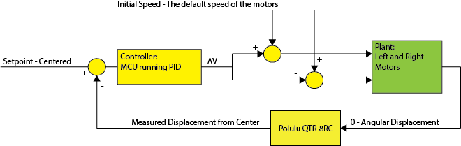
The line following algorithm utilizes a piece of control theory known as Proportional-Integral-Derivative (PID) control. The integral piece is not used in this application, so it is sometimes referred to as just PD control. The right describes the control loop in block-diagram form. Measured displacement from being centered on the line is used to calculate a difference in motor power between left and right motors. This is added to the initial speed for one motor and subtracted from the other in order to rotate the vehicle such that it veers back onto the line.
|
|
Flow Chart Overview